How to Install Agency Power Handbrake Kit for Can-Am Maverick X3
With this quick guide, you can add a hydraulic handbrake to your Can-Am Maverick X3. Handbrakes are not only fun, but they can help position the X3 near the limit. We recommend this handbrake for experienced drivers only. This product is intended for off-road use only. We recommend checking all components for proper operation before installation and use.
A PDF version of these instructions can be found HERE
Install Difficulty
Estimated Install Time
Roughly 2-3hrs with brake bleeding
Included Parts
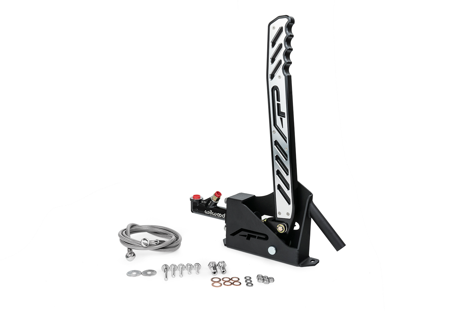
(1x) Handbrake Assembly
(1x) Braided Brake Line
(1x) 3/8-24 x 20mm Banjo Bolt
(1x) 7/16-20 x 24mm Banjo Bolt
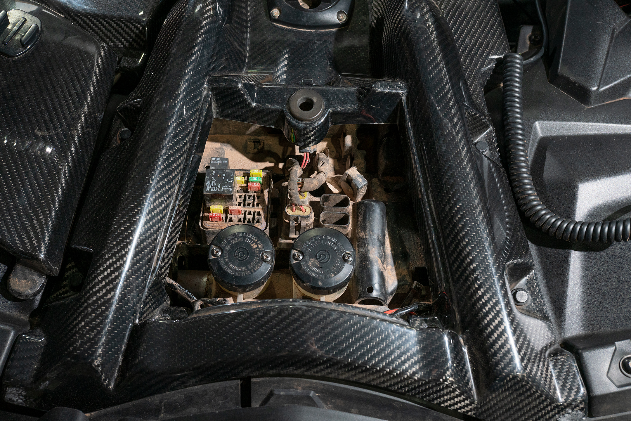
(4x) 10mm Copper Washer
(2x) 7/16″ Copper Washer
(1x) M6 x 35mm Flanged Hex Head Bolt (Front)
(2x) M6 x 25mm Flanged Hex Head Bolt (Lower)
(2x) M6 x 16mm Flanged Hex Head Bolt (Upper)
(3x) M6 Washer (Lower/Front)
(2x) 1/4″ ID 1″ OD Washer (Upper)
(5x) M6 Nyloc Nuts
Additional Parts Needed
DOT4 Brake Fluid
Removal
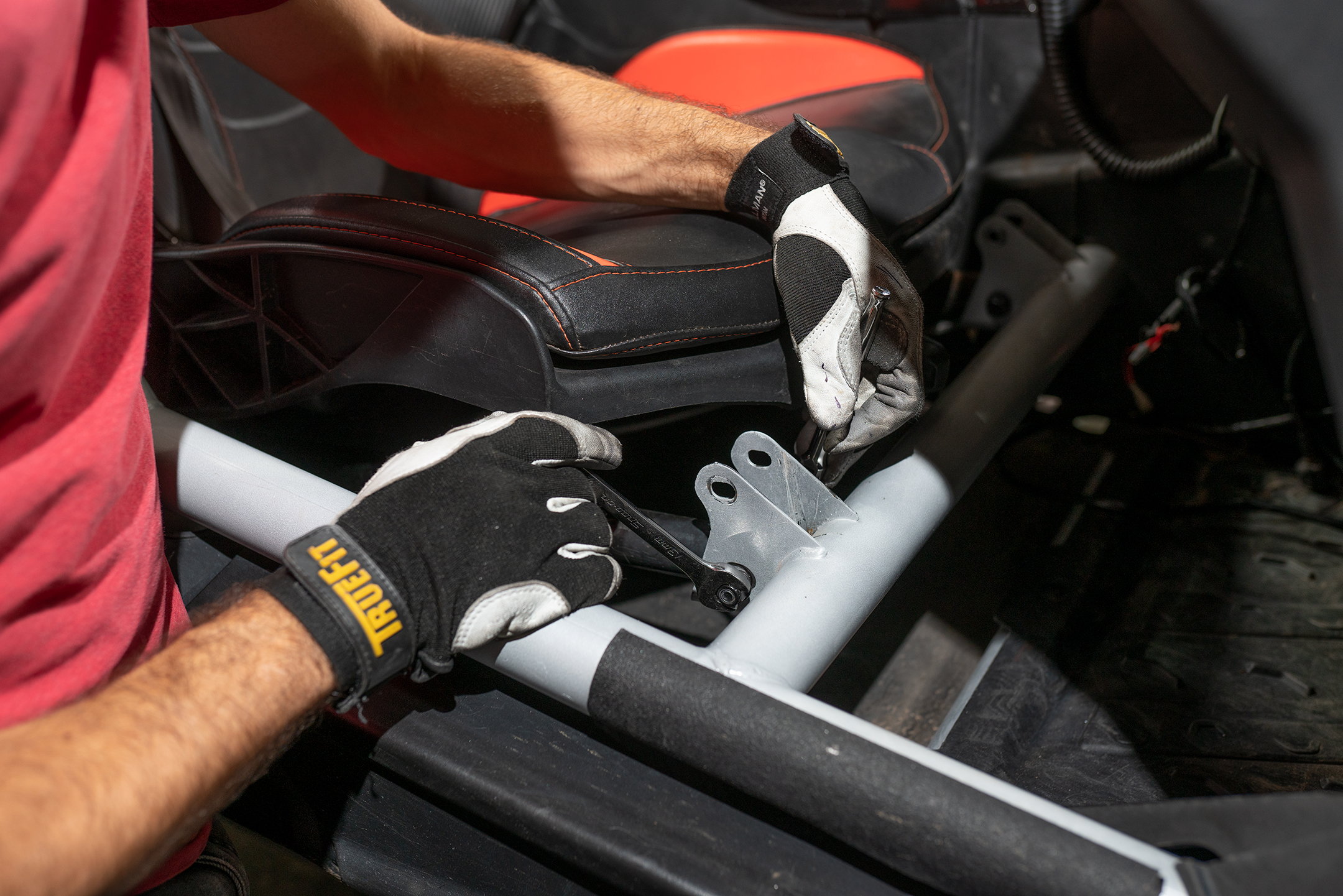
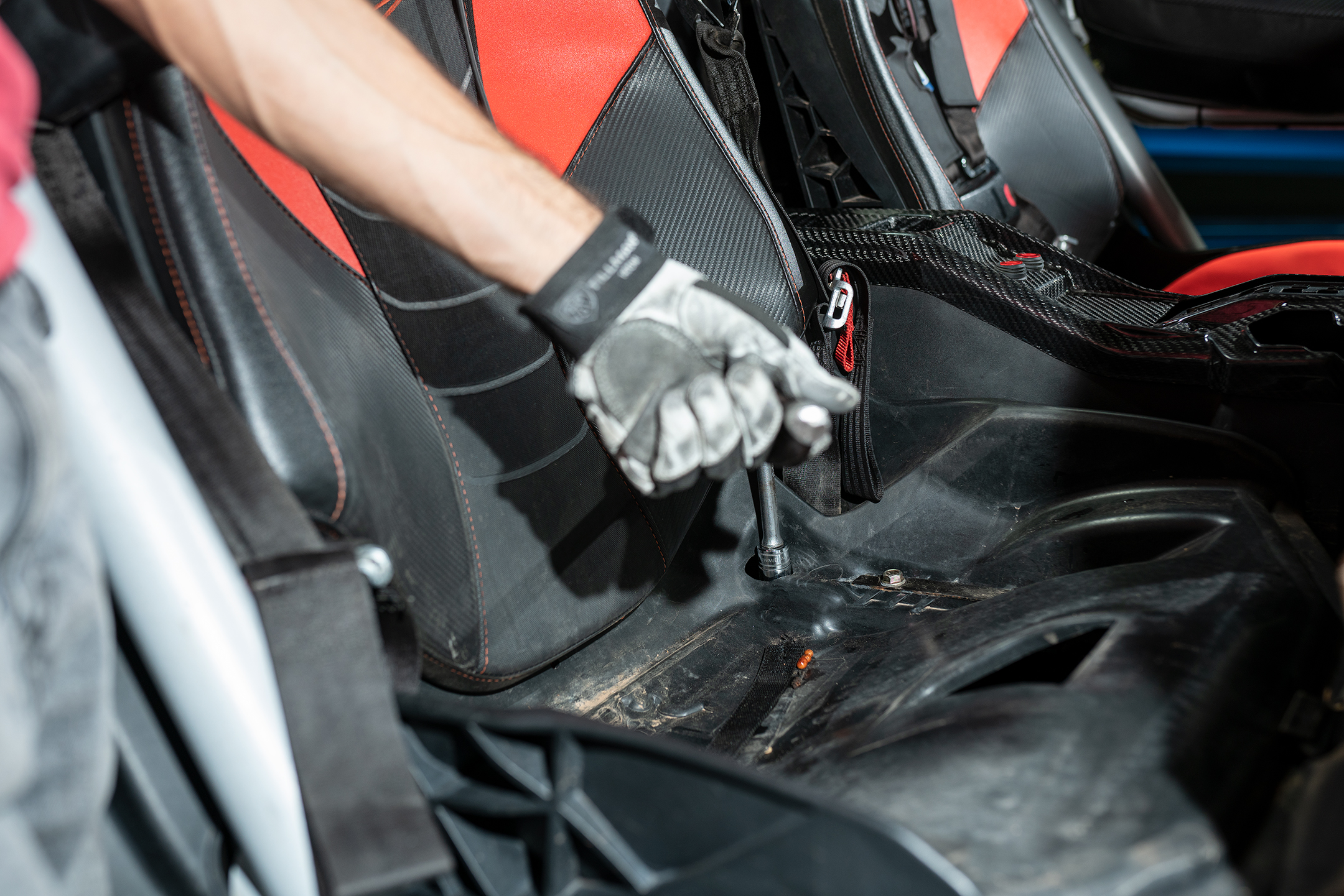
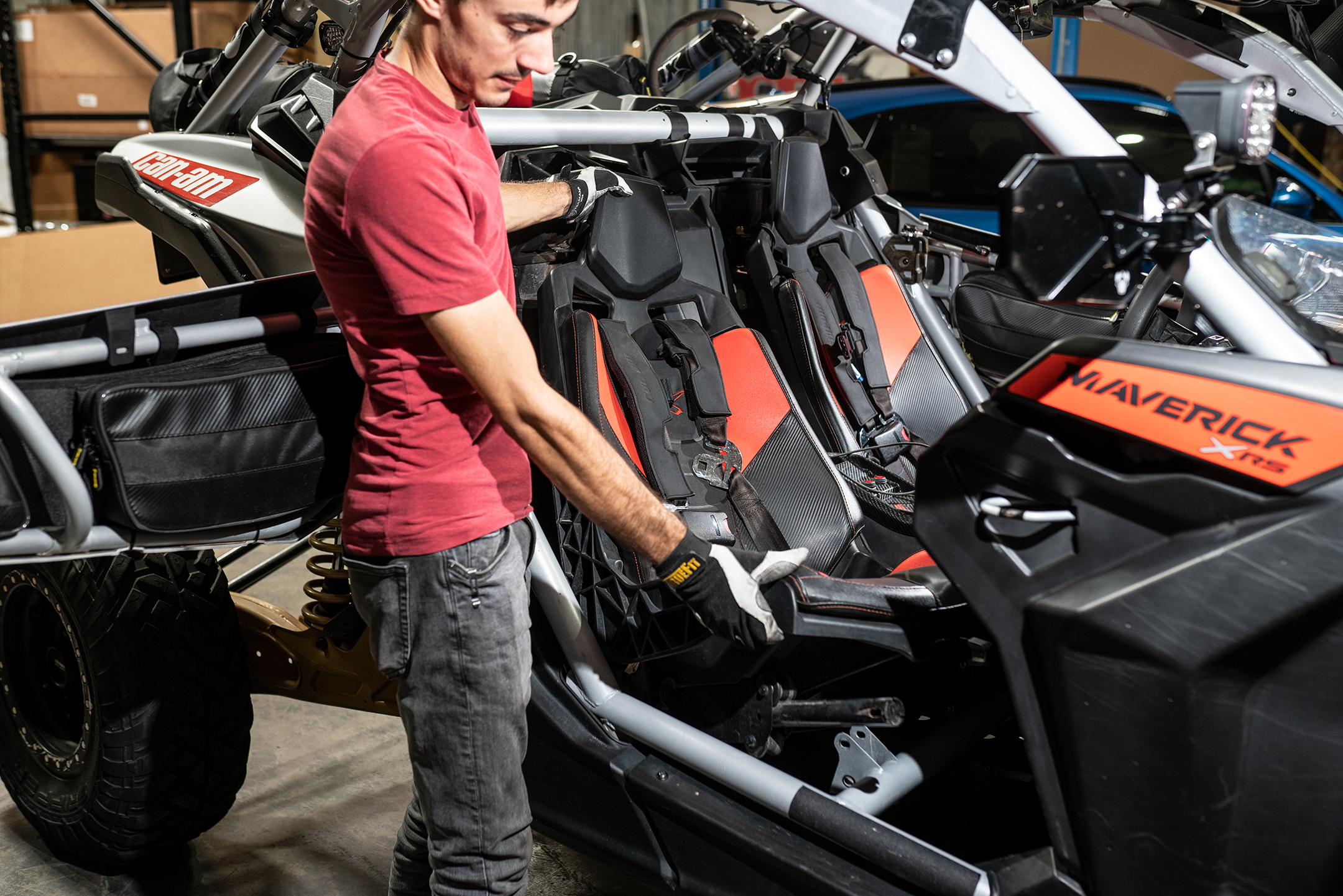
1. Remove the seats in the X3. We only removed the passenger side, but removing both sides makes for an easier installation.
2. Unbolt the front of the seat from the support. Remove the seat bottom to gain access to the rear bolts. Unbolt the rear from the rear bulkhead.
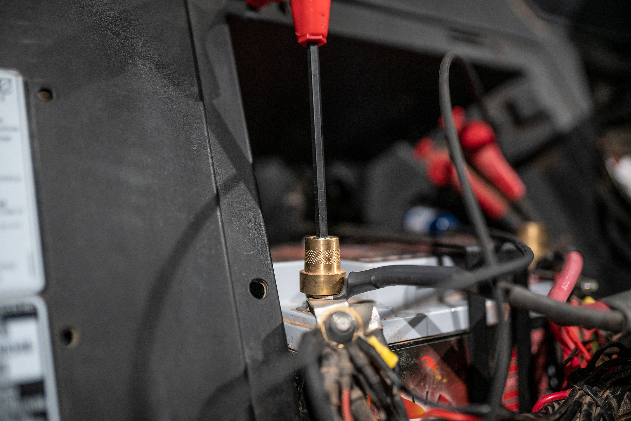
3. Disconnect the battery.
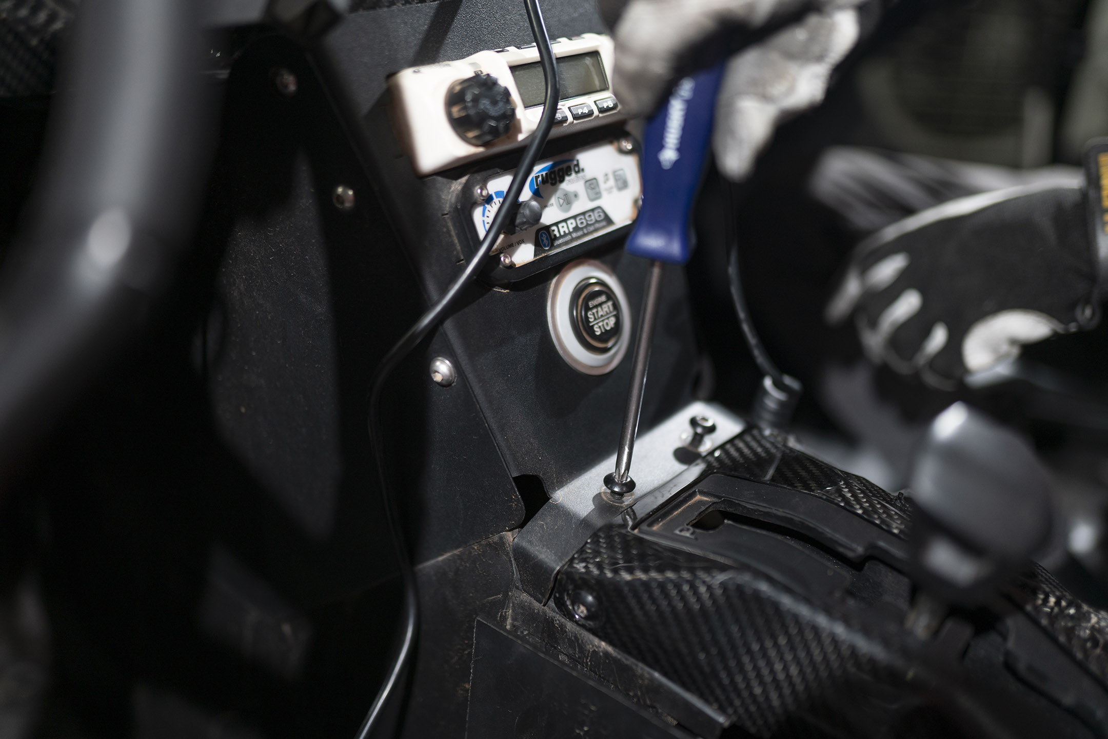
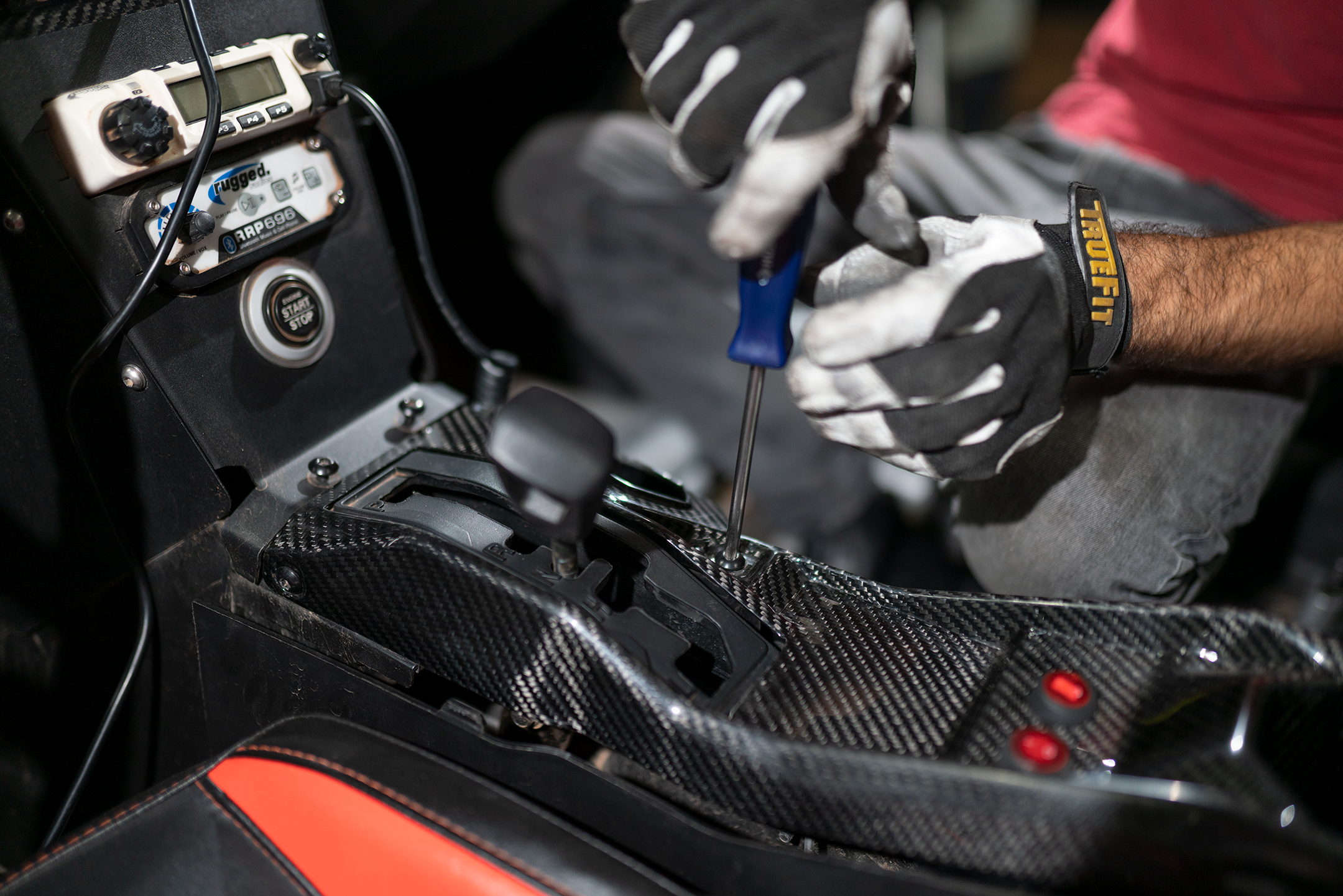
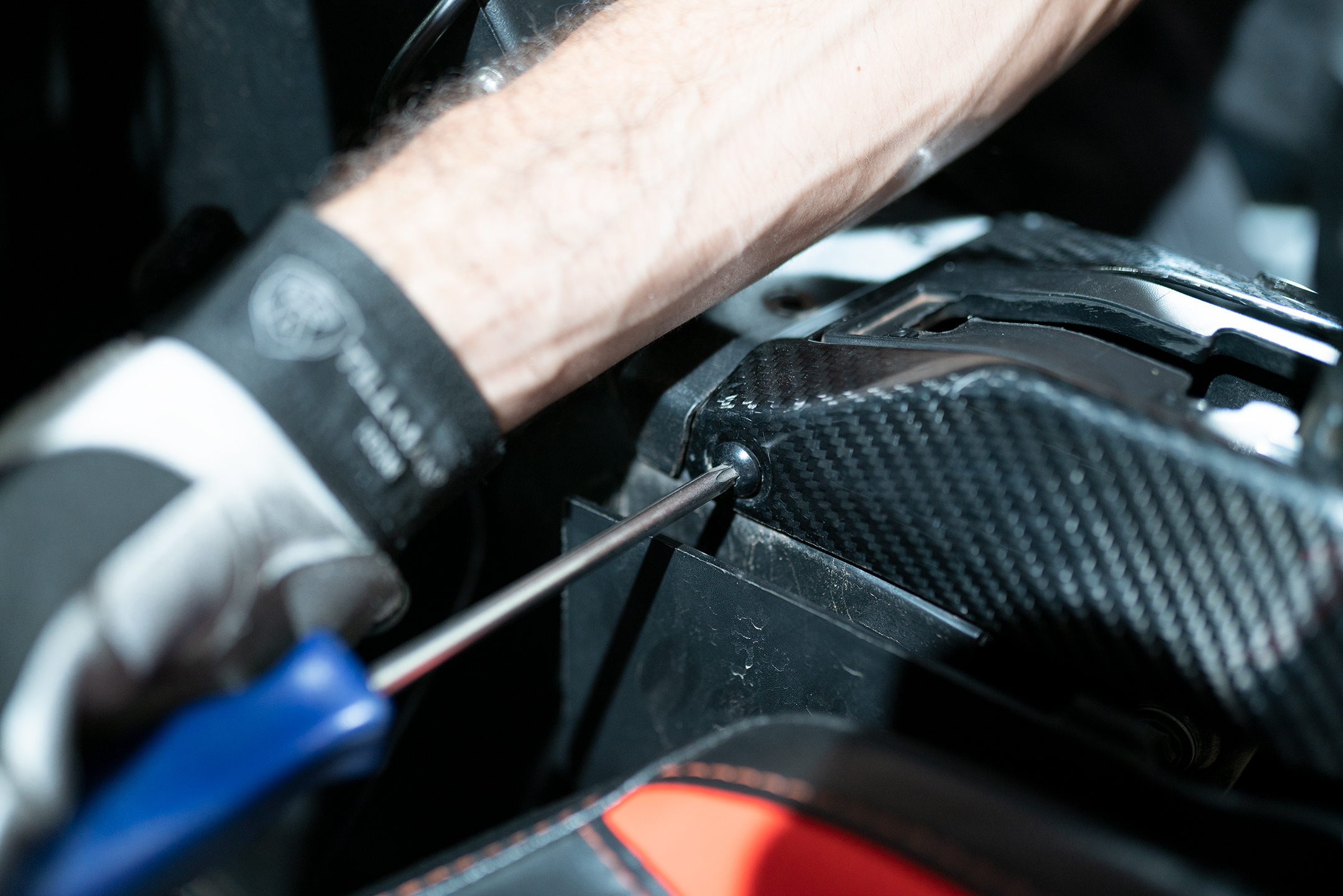
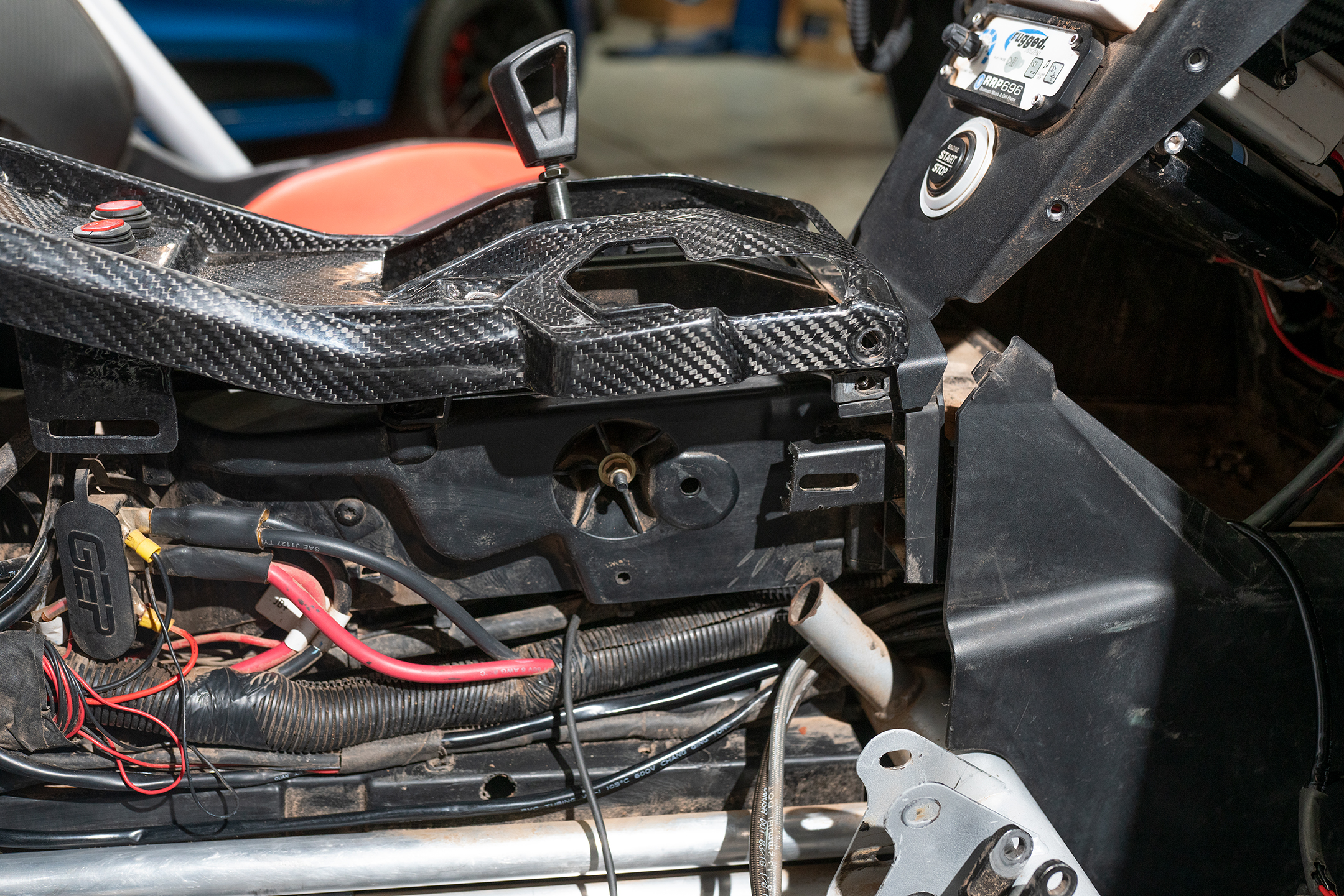
4. Removed passenger side grab handle grip. Remove the top and passenger side center console panels.
5. Remove the factory shift gate. This will allow access to the upper mounting holes.
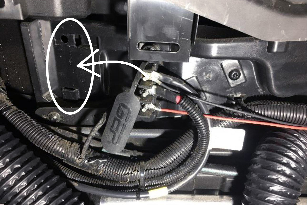
6. Relocate the power distribution block and clip towards the rear of the vehicle.
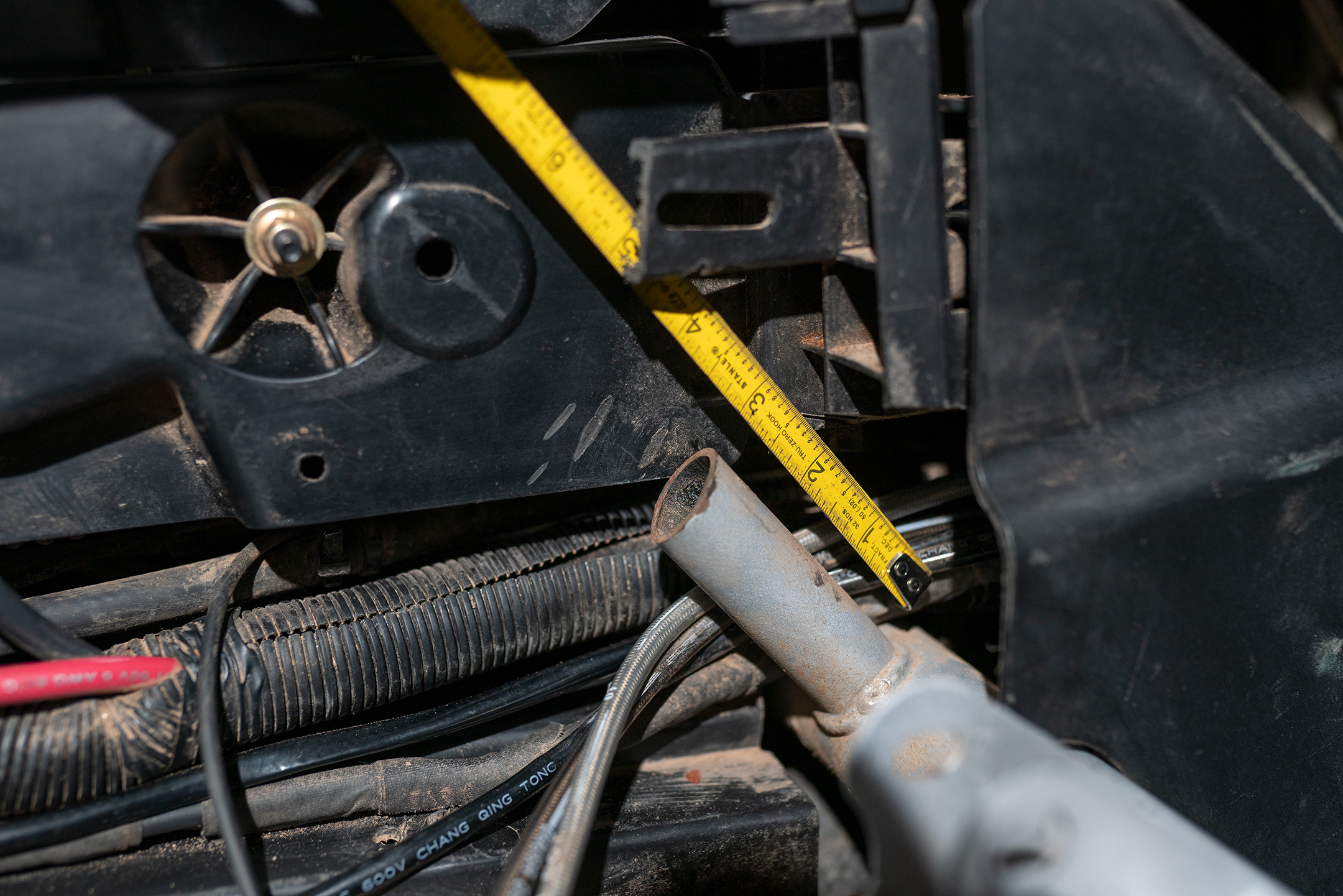
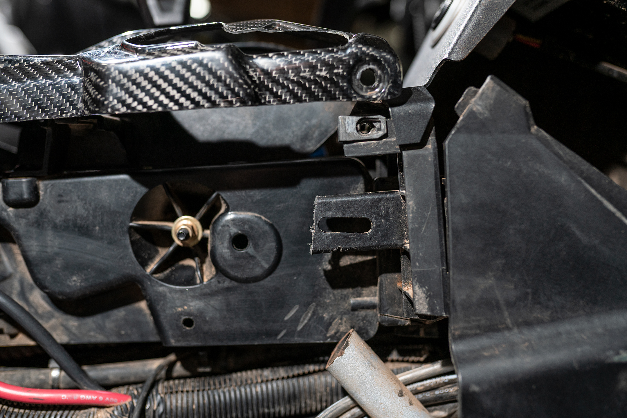
7. Cut the passenger grab handle. This should be 2-3″ from the frame.
NOTE: Avoid damaging any brake lines, coolant lines, wiring, or panels.
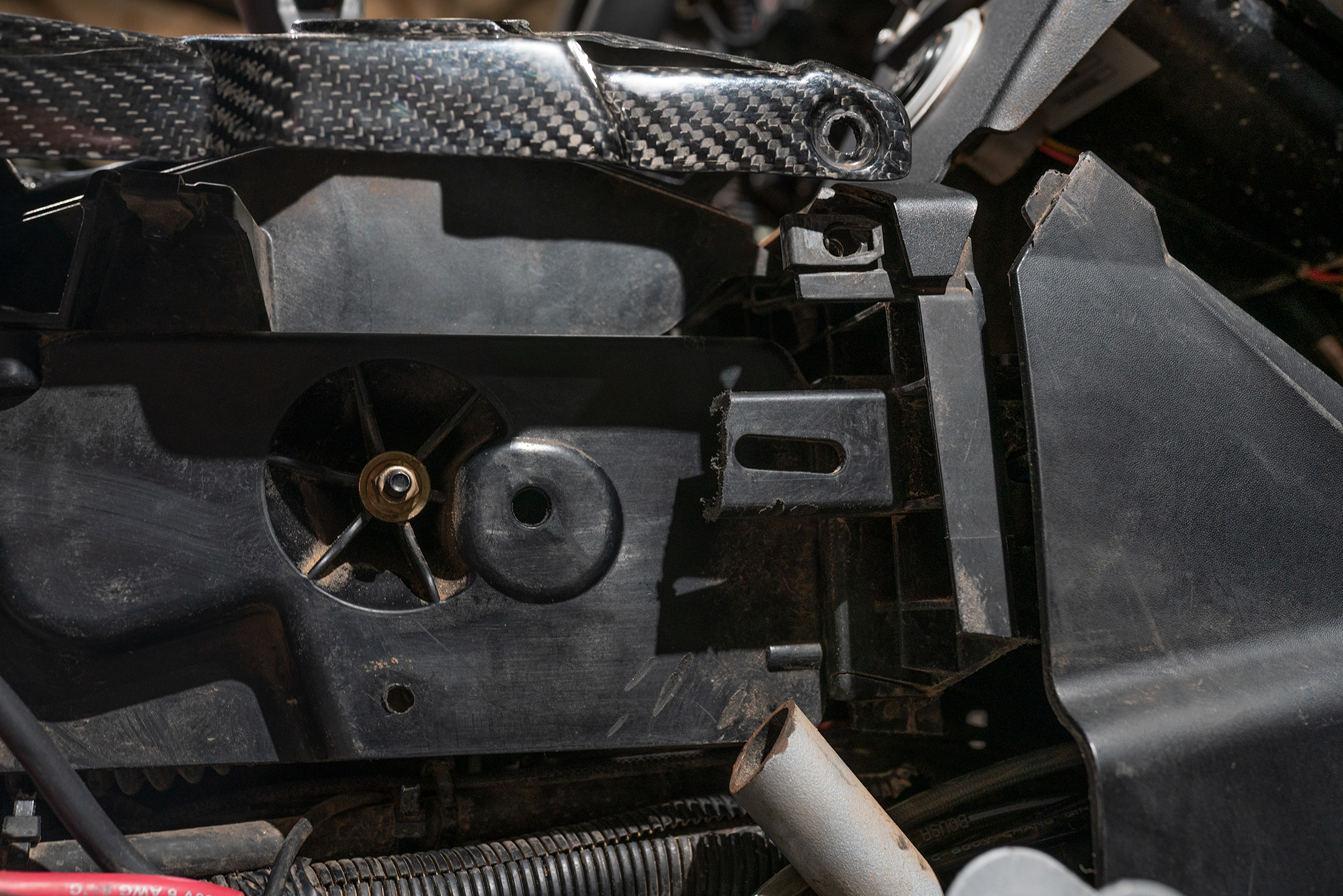
8. Trim the interior plastic tab as shown and tuck the wiring harness below the remaining piece of the grab handle tube.
Note: When installing the bracket, route the harness and fuel lines behind the bracket to avoid damage
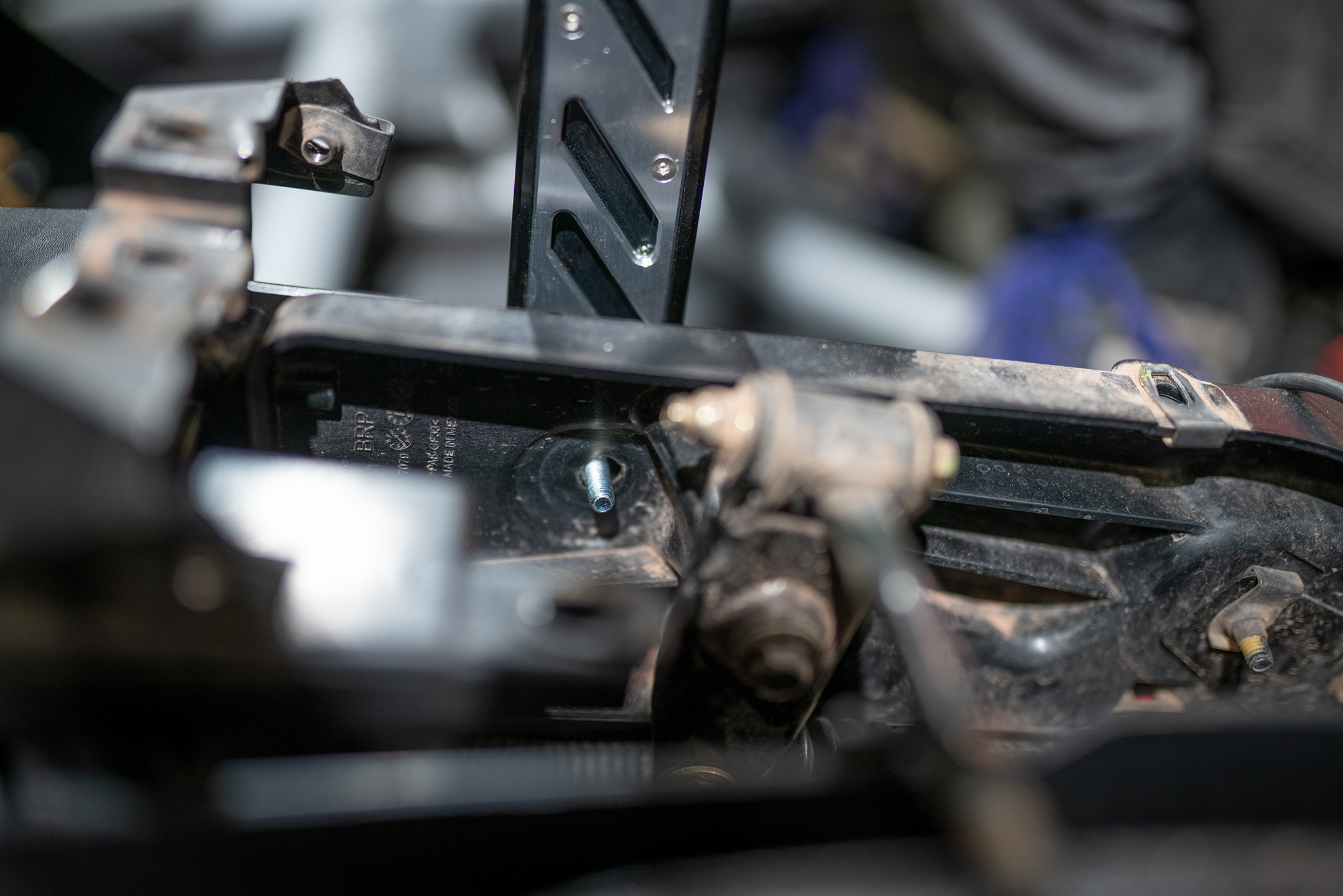
9. Install the handbrake into the grab handle tube. Line up the upper mounting holes with the side of the console. Install the M6 x 16mm bolts, large 1/4″ ID 1″ OD washers, and M6 Nyloc nuts through upper bracket mounting holes. The base should sit flat against the bottom of the console.
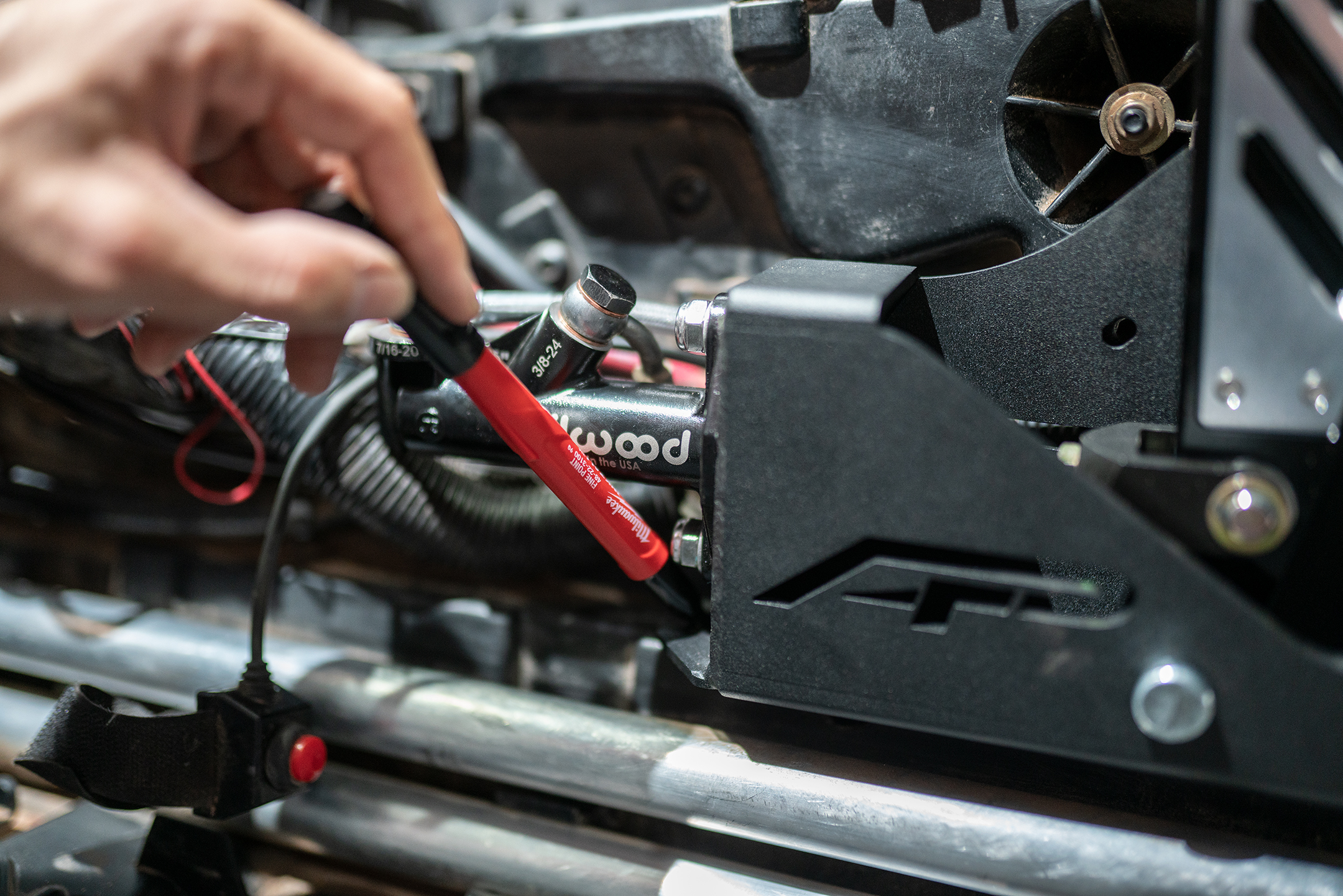
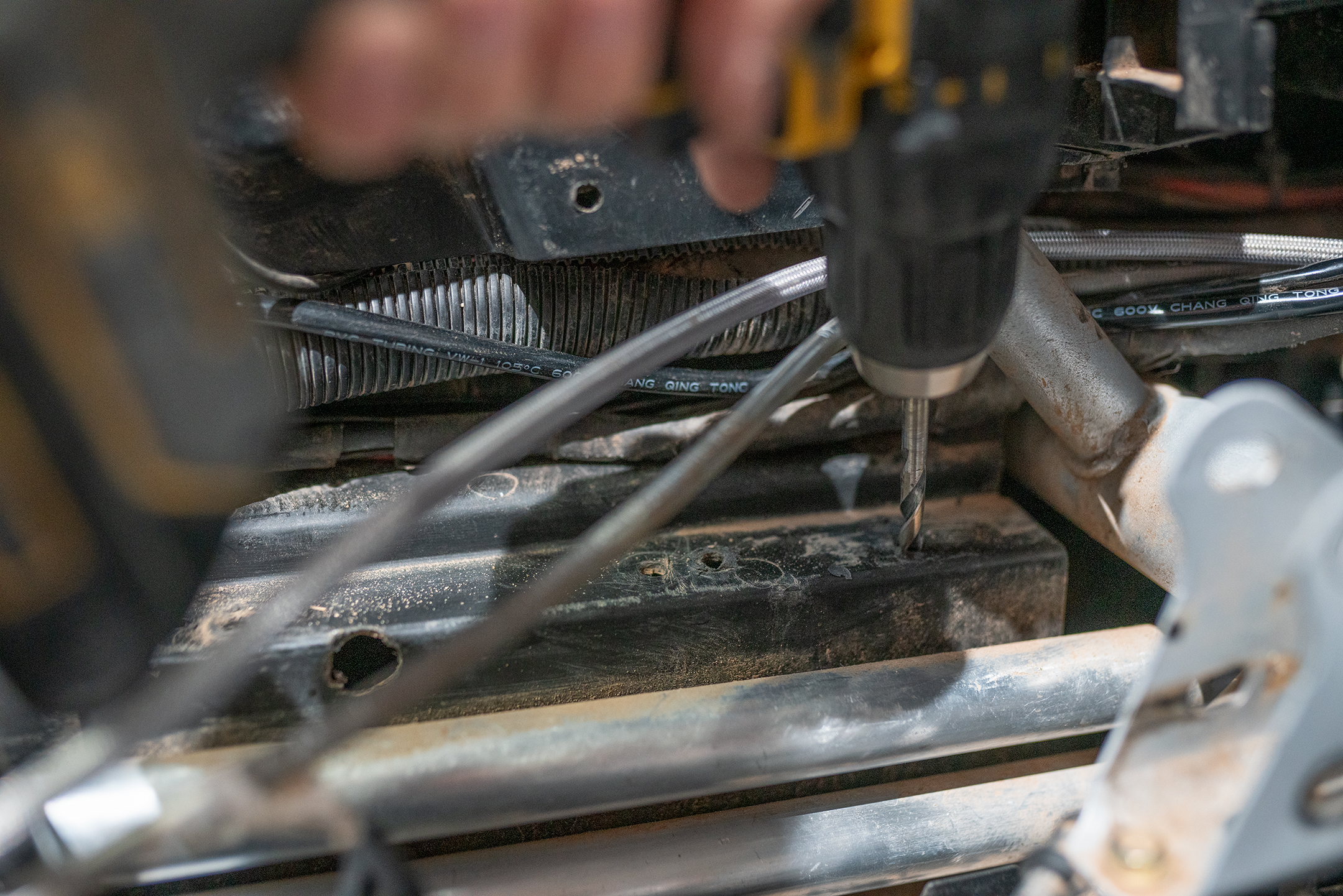
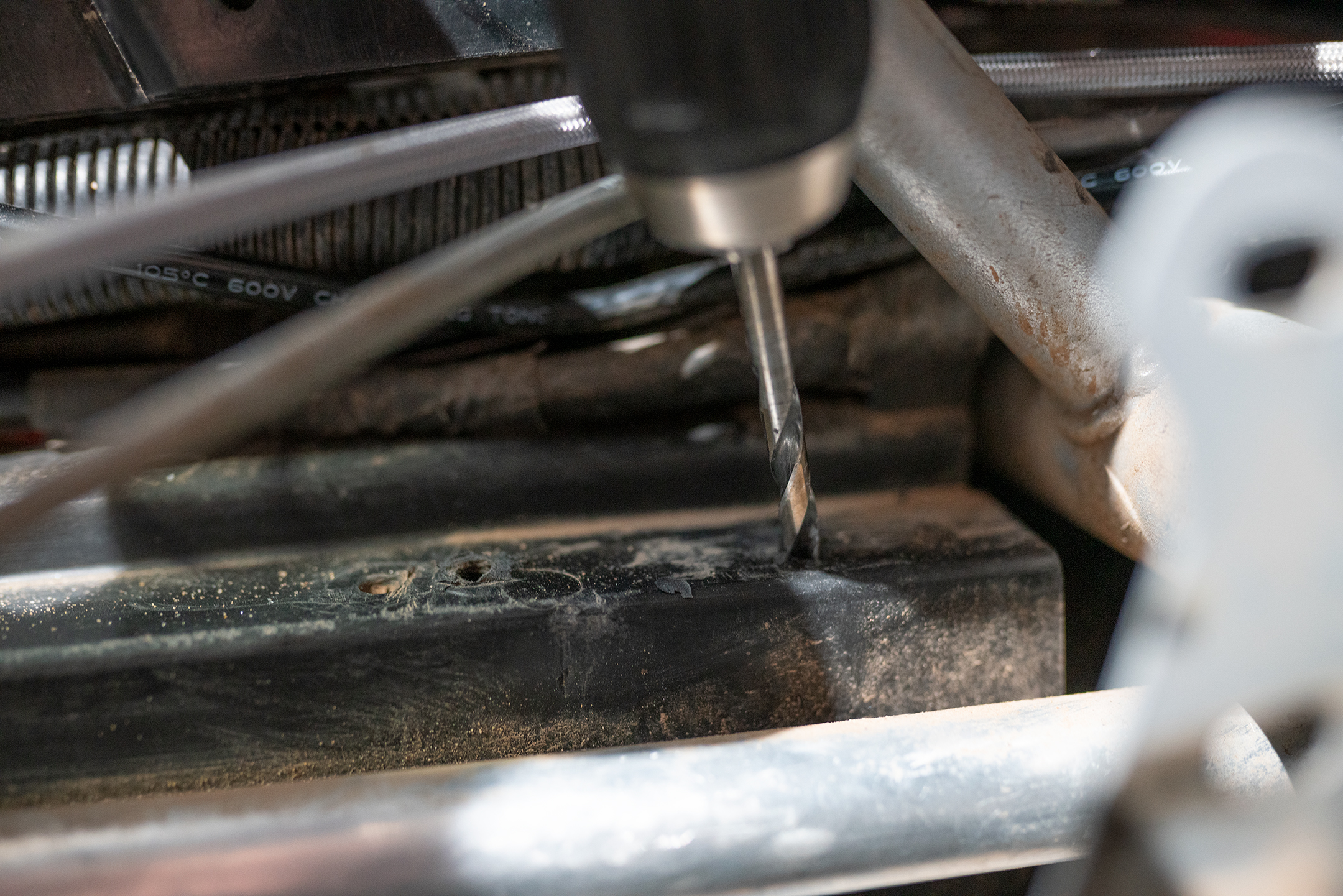
10. Mark where the handbrake base meets the console. Remove the handbrake and carefully drill 1/4″ holes into the center console.
NOTE: Avoid fuel lines, coolant lines, and wiring harnesses.
11. Disconnect the rear brake line from the master cylinder. (Farthest from the firewall) Connect the new stainless line to the master cylinder with new 10mm crush washers.
12. Route the brake line beneath the dash and to the other side. Route the brake line under the center console for the most clearance. Connect the line to the handbrake master cylinder, farthest port from the bracket using the 7/16-20 x 24mm banjo bolt. Connect the factory brake line to the second port, closest to the bracket using the 3/8-24 x 20mm banjo bolt.
NOTE: It is recommended to zip tie the brake lines away from any moving parts that can damage the line.
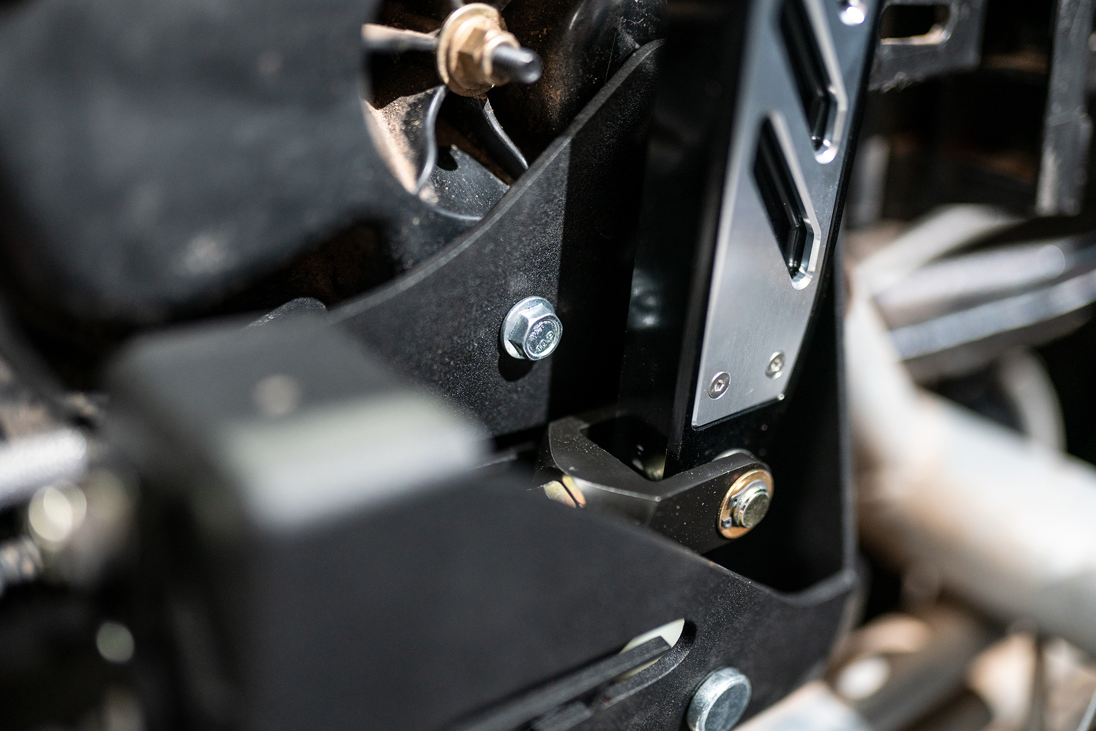
13. Reinstall the handbrake assembly to the console. Line up the upper mounting holes with the side of the console. Install the M6 x 16mm bolts, large 1/4″ ID 1″ OD washers, and M6 Nyloc nuts through the upper bracket mounting hole.
14. Install the M6 x 25mm bolts, small M6 washers, and M6 Nyloc nuts through the newly drilled lower mounting holes.
15. Recommended for additional stability: Drill a 1/4″ hole through the factory grab bar tune and Agency Power front handbrake mount. Insert the M6 x 35mm bolt through the hole and secure it with an M6 washer and Nyloc nut.
16. Fit the top Center console trim. Adjust the handbrake pushrod until the handbrake nearly touches the trimmed bracket. Ensure the handbrake has full range without interfering with the center console.
17. At this point we recommend bleeding the brakes. When bleeding the rear brakes, you may need to work the handbrake to work the air out of the system. Brakes should feel firm and like normal. Check for leaks in the system.
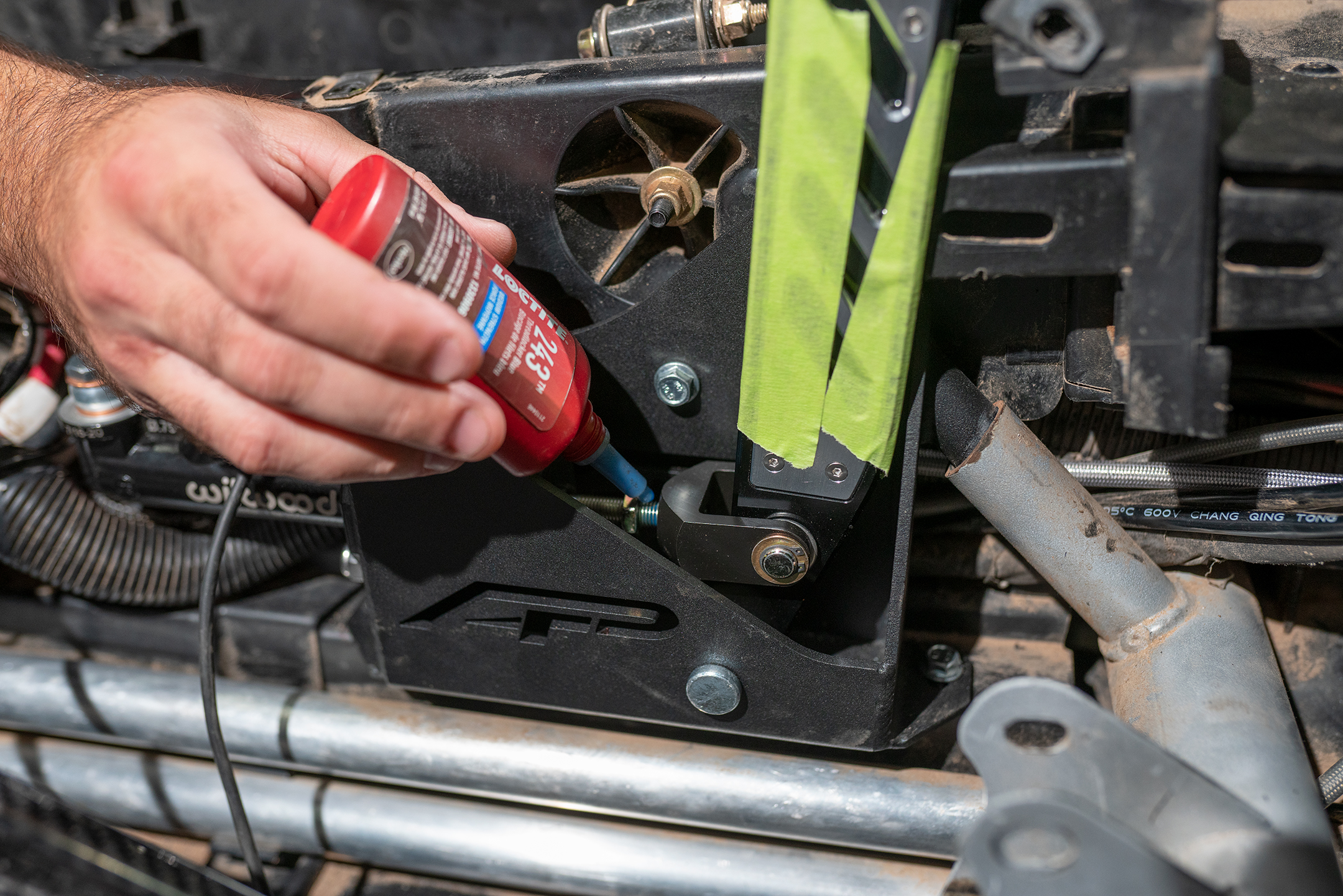
18. Additional handbrake adjustment may be necessary. Apply blue Locktite to the adjustment nut once the final location has been determined.
19. Road test vehicle before final assembly. If there are no problems, reassemble the interior, connect the battery, and reinstall the seats.
20. Enjoy sideways driving responsibly.








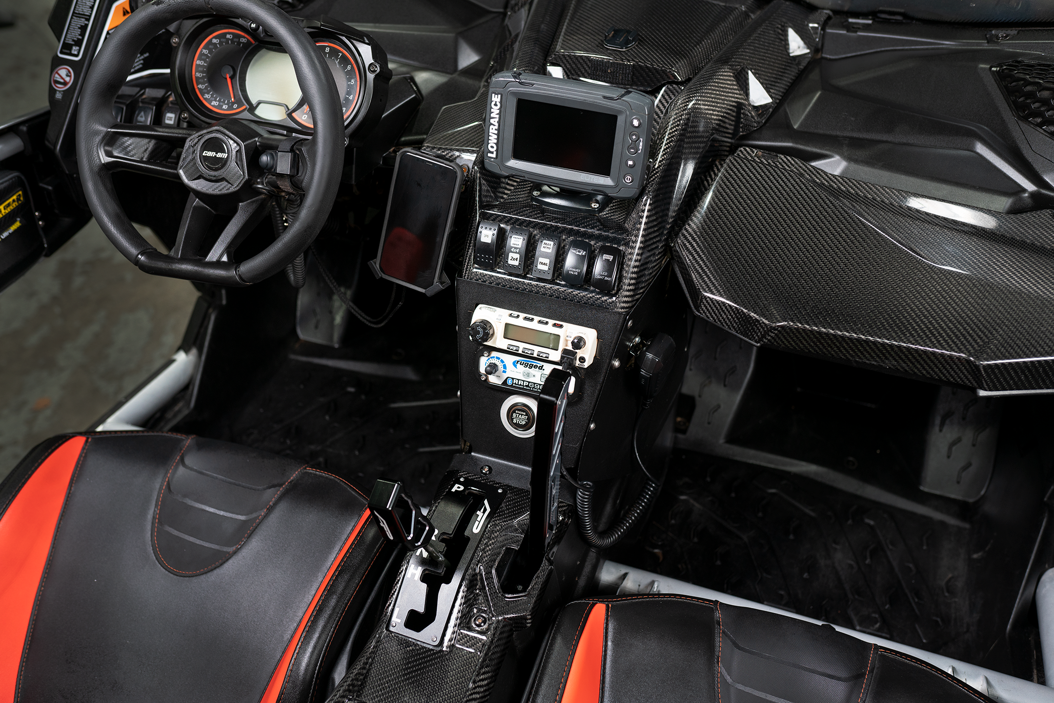


Nice work guys! Looks awesome!
Thank you